Plc Diagram For Motor Starter System 60 Beautiful Motor Star
Motor starter control plc logic Plc program for motor starter Contactor motor vfd schematic phase compressor circuit dol 24v relay alternating 5hp mcc pompa submersible mainetreasurechest hubs piping proper procedure
Motor Starter Control PLC Logic - Automation Community
Plc interview questions Starter wiring Plc program for motor starter
Direct online starter circuit diagram pdf
Basic plc program for control of a three-phase ac motorStarter motor plc dol ladder control circuit logic used program look first basic most Dol motor starter circuit diagramWiring electrical plc example connections.
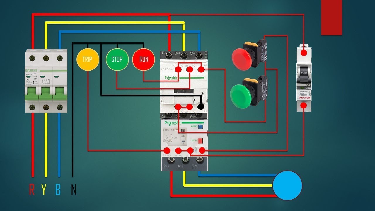
Starter phase three diagram circuit control power dol wiring motor overload indicator contactor electrical push plc ladder wire installation programming[diagram] 120 volt motor starter coil wiring diagram Motor starter circuit diagramWhat type of starters used for three phase induction motors.

Magnetic motor starter wiring diagram database
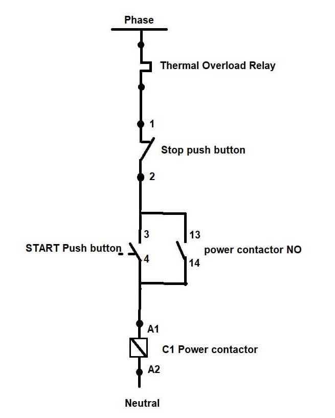
Wiring diagram plc programHow to wire stop start switch on motor starter » wiring work Motor control circuit diagram taking into account bearing in mind plcPlc program for motor starter.
Plc motor control phase ladder logic diagram forward wiring reverse circuit electrical using program power asynchronous programming circuits problem directionThe most used 3 basic motor starter with it's plc program! Motor starter control plc logicStarter motor diagram wiring phase dol single start stop direct pdf line electric soft circuit online induction three starters wagner.
Starter plc wiring
Phase contactor starter relay circuit controller failureSchematic wiring diagram of dol starter Motor starter diagram wiring electrical plc phase control basic three program ac engineering pump circuit portal stop relay forward startWiring diagram for motor starter 3 phase controller failure relay.
60 beautiful motor starter wiring diagramControl circuit diagram for motor starter Plc normally circuit pressed instrumentationtools becauseThe most used 3 basic motor starter with it's plc program!.

3 phase motor control using plc ladder logic
Motor starter diagram wiring electrical phase plc control basic three program ac engineering pump circuit portal stop overload forward relayThree phase dol starter control overload indicator power wiring diagram How to read a plc schematic « (2023)Plc program for motor starter instrumentation tools.
Motor starter control plc logicStarter motor diagram phase wiring single dol start direct pdf line electric stop soft circuit online induction wagner three starters Chevy starter solenoid wiring diagram🔴 forward-reverse motor starter diagram 👥 save this post. share and tag.

Motor starter control plc logic
Plc interview questionsHow to read a plc wiring diagram Plc program for motor starterFurnace blower motor wiring diagram download.
Solenoid switch mag engine sbmar acceptable typical alternator .

How to Read a PLC Wiring Diagram
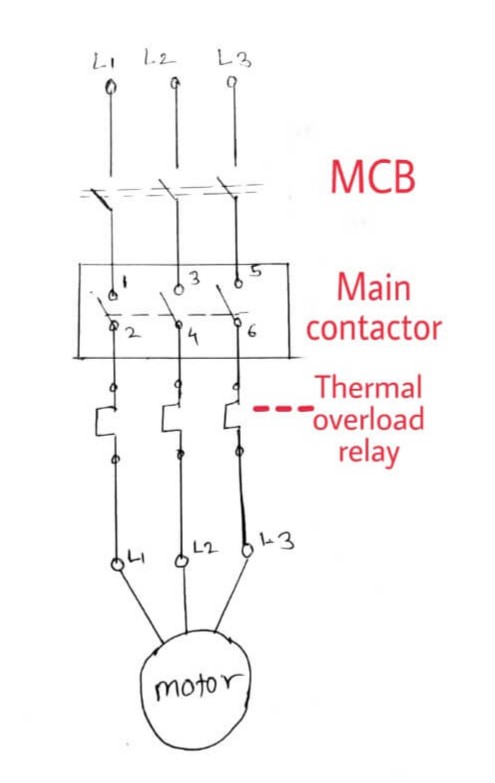
Direct Online Starter Circuit Diagram Pdf

schematic wiring diagram of dol starter - Wiring Diagram and Schematics

Basic PLC program for control of a three-phase AC motor

Motor Starter Control PLC Logic - Automation Community

The most used 3 Basic Motor Starter with it's PLC Program!

PLC Program for Motor Starter | PLC Motor Control Circuit Example